
What fasteners do I use to attach framing pieces together?
Most of our perimeter frames do not require fasteners for assembly; they are designed with an interference fit similar to the concept of Legos. For systems designed with a slip
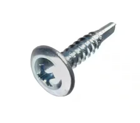
Most of our perimeter frames do not require fasteners for assembly; they are designed with an interference fit similar to the concept of Legos. For systems designed with a slip fit and for placing all of the omega intermediate supports, screws or rivets can be used to attach framing pieces together. The general practice is to use #8 sheet metal screws first. If you are pre-drilling a pilot hole, then standard point sheet metal screws can be used. If you prefer not to pre-drill, then self-drilling screws can be used. Head size, style, and length will vary depending on the framing system, placement, and personal preference.
Pro Tips:
- Make sure that fastener heads do not interfere with clearances for installing other components and make sure protruding exposed screw points don’t present a safety hazard.
- Torque your drill down to about 5 or 6 to avoid stripping out your screw hole. Slowly increase the torque to find the ideal setting on your drill. If and when a hole is stripped out, go up to the next fastener size in the same hole (that’s why you typically start with a #8; it gives you the option to go to a #10 or even #12 if your technician is having a bad day).
The most common rivet sizes are 1/8” diameter with ¼” grip and 3/16 with a ¼” grip. The length of the grip may change depending on what you’re trying to accomplish.
A few framing systems with nylon omega joints require specific lengths of screws when attaching intermediate support assemblies.
- 140-25 Systems – A minimum 1-1/8 inch screws when using GFG240-25
- 150-25 Systems – A minimum 1-1/8 inch screws when using GFG250-25
- 150-45 Systems – A minimum 1-1/8 inch screws when using GFG250-45
- 130-25 Stopper System – A minimum 1-1/4 inch screws when using GBP240-25
- 150-45 Stopper System – A minimum 1-3/4 in screws when using GBP250-45
- 150-45 Thermal Break Stopper System – A minimum 1-3/4 in screws when using GBP250-45
- 150-50 Thermal Break System – A minimum 1-3/4 in screws when using GBP250-45
- 140-25 Thermal Break Systems – A minimum 1-1/8 inch and 1-1/4 inch maximum length screws when using GFGTT240-25
- 160-45 Thermal Break Systems – A minimum 1-1/8 inch and 1-1/4 inch maximum length screws when using GFGTT260-45
Related posts
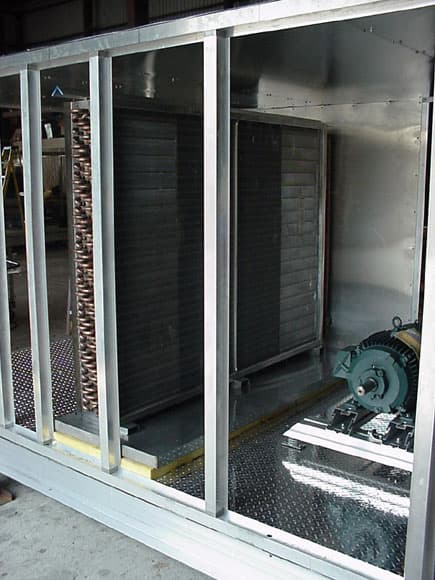
How do I know how tall the frame needs to be for my coil and drain pan?
There are numerous factors that go into properly designing the correct fit between your box and coil. The notes below are for general reference use only and serve only as
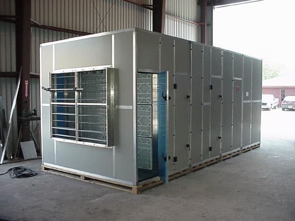
How do I size panels and account for the appropriate clearances?
** The standard production tolerance on panels is +/- 1/16in. For fixed panels, most customers allow for a 1/16in reduction in size from the panel opening. When considering production tolerances
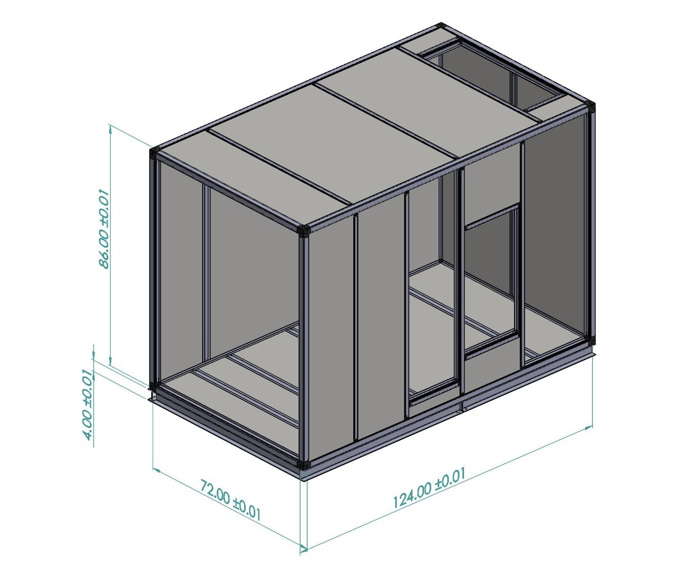
How do I calculate my cut lengths for the different framing systems?
Calculating the cut length on extrusions is most commonly done by deducting the exposed portion of the corner joints from the overall desired outside dimensions or you box. For example: